Label Definitions
Plant Modeller drawings, isometric drawings, and P&I diagrams can display labels that provide information about the objects shown in the drawing or diagram. For example, isometric drawings can use labels to display part numbers and material information, as shown below.
The labels are generated with configurable label definitions whose main constituents are the parametric 2D symbol that provides the label's graphical representation and the label text that can include information extracted from the COS database or, in the case of Diagram label definitions, the SQL database.
The project administrator prepares the required label definitions in the library or the project database. The label definition defines which object types can use the given label, and what is shown as the label text. There are some predefined label definitions in the CADMATIC example project that can be used as templates for new ones.
Creating label definitions
You can create a separate label definition for each label type that designers will be inserting into drawings. You can create the label definition from scratch as described below, or you can make a copy of an existing label definition and use that as a template.
Prerequisites
-
Optionally, an icon that shows what an inserted label will look like. See Icons.
-
Optionally, a script that inserts specific information into the label.
Do the following:
-
Open the Project Environment dialog:
-
In the CADMATIC desktop, select Object > Library and Project Databases.
-
In Plant Modeller or P&ID, select File > Environment > All library and project.
-
-
Browse to [library or project] > Document Production > Label Definitions.
-
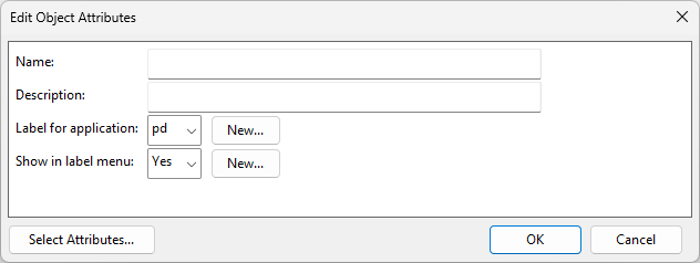
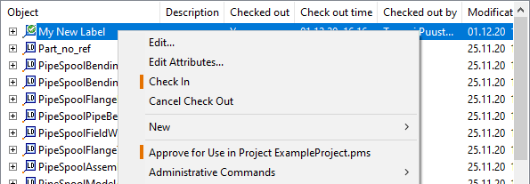
Select New > Label Definition. The Edit Object Attributes dialog opens.
-
Specify the attributes of the label definition:
-
Name – Enter a descriptive name for the label definition.
-
Description – Optionally, enter a more detailed description of the label definition and its intended use.
-
Label for application – Select the application where the label definition will be used: pm (Plant Modeller), pi (Piping Isometrics & Spools) or pd (P&ID).
-
Show in label menu – Select whether to list this label definition when the user is selecting a label definition in the application.
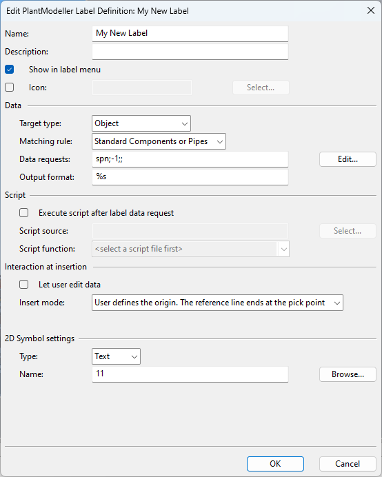
Then click OK. The Edit <application> Label Definition dialog opens.
-
-
Define the Label definition settings and click OK.
-
If you created the label definition in the library database, approve it for use in the project. If you edit the label definition after this, remember to perform a Check in.
-
Add the new label definition to Labeling Styles that target the required application and are approved for use in the project.
-
If you created the label definition via the application, restart the application and check that the label definition is now available in the label insertion tools.
Label definition settings
The settings in the Edit <application> Label Definition dialog define how the labels are to be generated. Many of the settings are common to all the applications, but some are application-specific. In this topic, we use [pm], [pi] and [pd] to indicate settings that only apply to specific applications.
Object attributes | eShare link [pm] | Data | Script | Interaction at insertion | 2D Symbol settings | Object [pd]
Object attributes
These settings were first defined when creating the label definition, but you can also edit them here.
- Name – Enter a descriptive name for the label definition.
- Description – You can provide a more detailed description of the label and its intended use.
- Show in label menu [pm, pi] – Select whether the label should be listed when the user is selecting a label in the application.
- Icon [pm, pi], Use icon [pd] – You can select a specific icon for the label definition.
eShare link [pm]
Plant Modeller label definitions that target objects can specify whether eShare should turn the label text into a hyperlink that can be clicked to show the associated object in the 3D model viewer.
-
Default link – Labels are linked to the 3D model as specified in Automatic object linking in eShare documents.
-
No link – Labels are not turned into hyperlinks.
-
Custom attribute – Labels are turned into hyperlinks based on the specified attribute:
-
COS object id (.pY)
-
Name of object's pipeline (pli)
-
Name of object's cable tray (.qz)
-
Name of object's ductline (.rR)
-
Object's system name (sys)
-
Data
These settings define what kind of object the user must select to insert the label and what is the data to be shown in the label.
Note: P&ID related data settings are described in Diagram label definitions.
-
Target type [pm] – Define the target of the labels in Plant Modeller drawings:
- Point – The label can be attached to a point to show information about that point.
- Connection – The label can be attached to a connection to show information about that connection.
- Object – The label can be attached to an object to show information about that object.
- Object & Connection – The label can be attached to a connection or seam to show information about that connection or seam and the connected object.
- Object & Point – The label can be attached to a node to show information about that node and its owner object. Objects without visible nodes in the drawing are skipped.
- Cables at Object – The label can be attached to a cable network node to list the cables at that location.
-
Target type [pi] – Define the target of the labels in isometric drawings:
- Special Axis Label – The label can be placed anywhere to show the coordinate axes.
- Object – The label can be attached to an object to show information about that object.
- Point – The label can be attached to a point to show information about that point.
- Free Label – The label can be placed anywhere to show a user-defined text in the drawing.
- Coordinate Label – The label can be attached to any user-defined point to show the coordinates of that point.
-
Matching rule [pm] – Define what kind of 3D object the label can be attached to:
-
If Target type refers to an object or connection, the Matching rule can be set to either 'Any or No Object' or a specific object type.
-
If Target type refers to cables, then Matching rule is always 'Cable Network Parts'.
-
-
Output format – Define the data to be shown in the label by entering a data request and its formatting. You can either type the values or click Edit to use the editor described in Edit Data Requests.
-
There can be one or more data requests. Each data request must be in the format r1;r2;r3; where r1 is the data source (tag), r2 specifies quantity type (-1 if non-numeric data), and r3 specifies the display format for numeric data (not defined for non-numeric data). Examples:
-
MC;-1;; retrieves Material Code as a text string
-
.mi;-1;; retrieves a list of cables from a Cable Network Part
-
-
There must be as many format strings as there are data requests; you can add other characters between the format strings to separate the values in the output or to indicate the meaning of the value (for example, add "NS" in front of Nominal Size values).
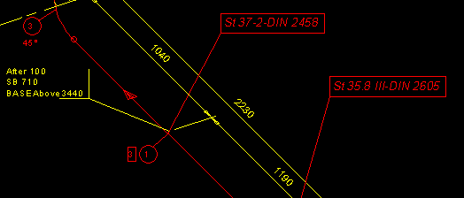
For example, if the data requests MC;-1;;ST;-1;; return a Material Code (MC) and Standard (ST) as text string values "St35.8 III" and "DIN2605", the output format %s-%s outputs the string "St35.8 III-DIN2605".

-
Script
You can use a script to create or modify the label text. The script can retrieve additional information from the application, and then either append this information to the label text or completely replace the label text created by the data request. The label text produced by the script is passed to the 2D symbol and shown in the label.
-
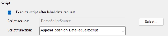
Execute script after label data request – Select this option to run a script after the label data request.
-
Script source – Click Select to browse for the script source.
-
Script function – Select the script function from the drop-down list.
In this example we use a script to insert position information and the name of the coordinate system after the position ID of a model object.
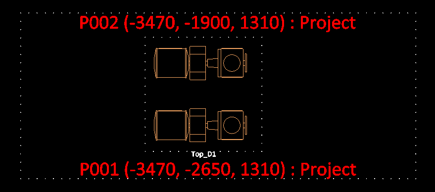
The script does not use the optional third argument of the data request script function that gets the name of the drawing view. It could be used, for example, to access the information of the drawing view.
#include "include/cos.h"
#include "include/dm_cos_schema.h"
#include "include/pm.h"
#include "include/dmutil.h"
#include "include/pm_core_tags.h"

/**
 * Appends position information (x, y, z) : coordinate system
 *
 * @param text [in/out]           Text received from the label data request. Can be modified.
 * @param drec [in]               Record containing the association data of a label, such as MMT_TAG_COSOID.
 * @param viewName [in, optional] Name of the drawing view where the label is located.
 * @return 0 success.
 */
Append_position_DataRequestScript(text, drec, viewName)
{
    x = DM_GET_TAGVAL(drec, MMT_TAG_ORIG_X);
    y = DM_GET_TAGVAL(drec, MMT_TAG_ORIG_Y);
    z = DM_GET_TAGVAL(drec, MMT_TAG_ORIG_Z);

    if (!ISSTRING(x) | !ISSTRING(y) | !ISSTRING(z)) {
        return -1;
    }

    x = 1.0 * x;
    y = 1.0 * y;
    z = 1.0 * z;

    coord_sys_oid = PM_GET_CURRENT_COORDINATE_SYSTEM();
    COS_READ_OBJECT(coord_sys_oid);
    attrs = COS_GET_OBJECT_ATTRIBUTES(coord_sys_oid);
    coord_system_name = DM_GET_TAGVAL(attrs, DM_COSA_NAME);

    coords_str = "";
    S_PRINTF(coords_str, " (%.0f, %.0f, %.0f) : %s", x, y, z, coord_system_name);

    text = text + coords_str;
    return 0;
}
Using this example code, the Script function field is set to get additional text for the label from the "Append_position_DataRequestScript" function.
Interaction at insertion
These settings define what happens when the user is inserting a label.
-
Let user edit data [pm, pi] – If selected, the user can edit the label data. For example, if the label is used as a note, then the user should be allowed to add notes to it.
-
Insert mode [pm] / Digit mode [pd] – Specifies whether the origin is at the pick point or defined by the user and whether a reference line is drawn (and modifiable) by the user.
2D Symbol settings
These settings specify the text style or graphical 2D symbol that the label is to use.
-
Type – Select whether the symbol is of type 'Text' (script-based text) or 'General' (a graphic symbol). In isometric drawings it is always 'General'.
If Type=Text, define the following:
-
Name – Select the text style to use by clicking Browse or typing just the number of the text style, such as 18 for 'text18' (text in a box with reference line).
If Type=General, define the following:
-
Name – Select the graphical 2D symbol to use by clicking Browse or typing the name of the symbol.
-
Scaling [pm] – Specifies whether scaling is inherited from the current view or defined by user. If defined by the user, specify scaling and rotation as described below.
-
Scale X, Scale Y – These specify the scale factors of the symbol in X and Y direction. The default scale 1.0 indicates that symbol units are the same as sheet units.
-
Rotation – Specifies the rotation angle of the symbol.
The project administrator can define new text styles and graphical 2D symbols in Project Environment > [library or project] > Document Production > 2D Symbols.
About 2D text symbols and label definitions
The 2D Symbol objects that are stored in the library database and used in labels should be approved for use in the project database. In [library] > Document Production > 2D Symbols > pi, the "PiUtils" COS object contains common utilities that are used by some of the 2D symbols delivered in the base setup, so also "PiUtils" should be approved for the project.
2D text symbols that are used in labels must be defined with standard arguments that depend on the application where the symbol will be used. For example, the 2D symbol txtboxrefl that can be used in isometric drawings has the following arguments:
-
box_text – The text string that data requests in the label definition retrieve from the database. The text can be processed in the text symbol before being written into the label (typically, by adding some separator characters between data requests).
-
du, dv – The vector from the symbol's origin to the reference point.
-
n_chars – The number of characters in the text string retrieved by box_text.
-
mm_fact – A conversion factor that converts local coordinates into mm (graphics unit).
Note: Be careful with symbol arguments—ensure that the number of arguments and the argument types are correct.
See
Object [pd]
Click Attributes if you want to add the attribute PD object standard (ISO, DIN, Cadmatic, not defined, JIS, IEC, or ISA) to the label definition.
Examples
Label Definition for Isometric Drawings
This label definition shows the Material Code and the Standard of a piping object in an isometric drawing.

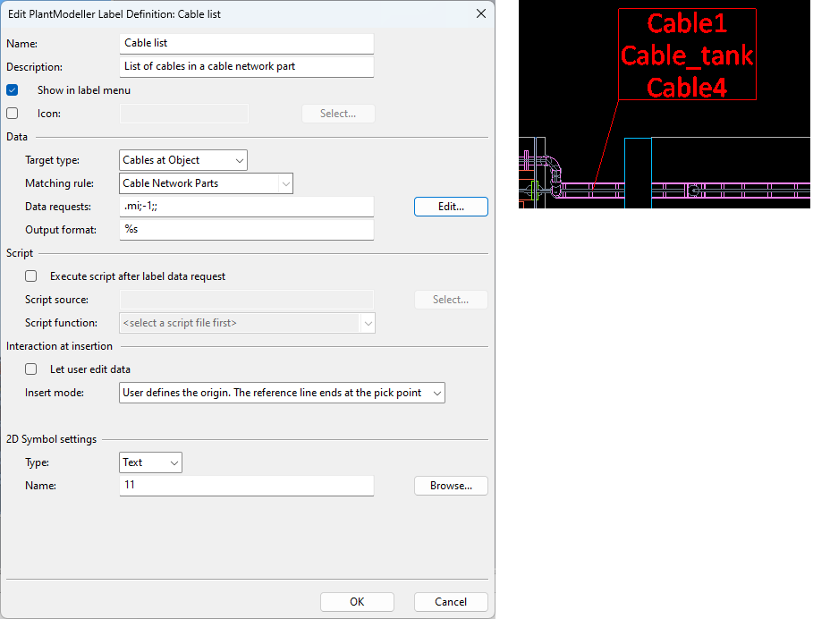
Label Definition for Cable Drawings
This label definition creates a list of cables that are located in a given Cable Network Part (segment or node) in a cable drawing.